|
|
By: Jason
Cuadra Experiment:
I took my AR M1 home speaker, which is a slim floorstanding 2way with an additional
6.5" bass driver in a sealed box at the bottom of the enclosure, and put it in the
trunk, with the bottom woofer close to where the spare tire was. (I drive around with an
inflator). The software I used, LAud, is great stuff - it does MLS, impulse response, FFT,
waterfalls, distortion, etc. It's at www.libinst.com.
I placed the mic at the driver's head position. I used LAud's Scripted automatic
measurements for nearfield bass. (It's just the most convenient script for 10-200Hz
measurements - and it includes flat gain correction for the nearfield vs. 1 meter anechoic
which I ignored, resulting in a +40dB shift or so) I saved both the impulse response and
frequency response.
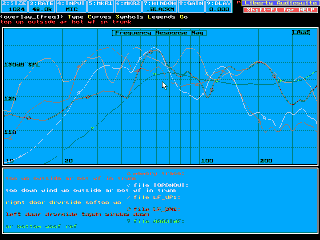
The gif file shows 5 plots (click on the graph to see a larger version). All are
1/3rd octave smoothed. The first 4 plots are the combinations of speaker in the trunk/door
speakers, and soft top up and down. The first 2 is for the trunk-mounted AR woofer. Number
3 and 4 are the door speakers. The 5th plot is the nearfield measurement of my AR bottom
woofer, which is equivalent to anechoic. As you can see the rolloff begins at ~50Hz. The
measurements are the electrical drive to microphone transfer functions, so to get the
car's cabin gain, you would have to subtract the AR woof's acoustic response from the mic
measurement. Note the curves are offset about 40dB up because of how I set my LAud preamp
and the nearfield gain setup.
I don't have nearfield measurements of my door speakers yet - I should go and
get them. But they're 6.5" by Vifa, the P17WGxxxx which I bought from Solen
(www.solen.com). Subjectively with the top up they have decent bass, (6mm xmax!) but
driven by 12W from my Panasonic head unit, isn't too loud. Their rolloff is supposed to be
~55Hz or so. I surface mounted them on the door panel, so I had to enlarge the holes, and
I had to fabricate spacer rings (about 13mm thick) to go between the door panel and the
door sheet metal. Screws hold down the spacer to the original screw holes in the sheet
metal in recessed holes, and 4 screws hold down the woofs, thru the door panel, into the
wood, but don't reach the sheet metal. So, no cutting or drilling of sheet meta. BTW my
tweets are the LPG26NA Aluminum dome neos - very nice, clean, smooth, soft-dome like
sound. (I don't like most hard domes).
Observations:
It seems the 50Hz sealed box complements the car's transfer function when the top is up.
Hopefully I'll have the time to measure with the hardtop too. When measuring bass
reproduced by 2 speakers (in the case of the door speakers) one is supposed to play them
simultaneously (see John Borwick's book, "The Loudspeaker and Headphone
Handbook"). I'd forgotten this fact so I hope to go back and measure that too. I
might take advantage of the reciprocity Expectedly you lose bass with the top down.
Unexpectedly and fortunately the effect is less pronounced for the trunk mounted woof than
for the door woofs. Waterfalls show mighty resonances at 60Hz (top up) and 30Hz (top down)
otherwise it looks reasonably well-behaved.
UPDATE: 14th December 1998
Did a 2nd set of Miata transfer function measurements - I took acoustical
measurements of both door speakers playing together, mic at the driver headrest, with the
top up and down. In the chapter "Subjective evaluation" edited by Floyd Toole,
in the book "Loudspeaker and Headphone Handbook" edited by John Borwick's, it is
suggested that bass measurements be made with both speakers of a stereo system playing.
Results are not appreciably different so I won't show them.
I did a nearfield of my 6.5" door speakers and measured the door speaker's
impedance curves to see if there was anything obviously out of line. Thiele-Small theory
shows that the impedance curve will predict the low frequency SPL curves of a
direct-radiator loudspeaker. Speakers are impressively good. Rolloff begins ~ 60Hz.
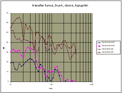
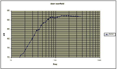
I used Excel to subtract the door nearfield measurement from the car measurements with the
door speakers playing, for top up and top down. This produced the transfer function for
the door speaker mounting location. Then I did the same, with the trunk-mounted speaker's
nearfield, and the in-car measurements with the trunk speaker playing. Here are the
results. Unfortunately I lost the mic amp gain settings so there are relative offsets
between the door curves and the trunk curves. It is possible that the trunk mounting loses
sensitivity due to the distance. Later when I build my sub box I will get accurate gain
measurements. However the curves will still show the relative frequency response of the
cabin gain.
Several things are apparent. 1st there is a definite rise at low frequencies for
all combinations. 2nd there is a definite loss when the top is lowered - more than 10 dB
from ~33 Hz down. Next, the loss due to lower the top is worse for the trunk mounting -
don't know why. Sometime later I hope to make measurements with the hardtop. (It's now
mostly gathering dust in my spare bedroom ).
About sub alignments, and EBS for a car:
Many people (Vance Dickason's book, "The Loudspeaker Design Cookbook" included)
have said that for a car a sealed box with a Q of 0.71 and a resonance of 55 Hz nicely
complements a typical car's transfer curve, yielding flat response. The same people say
that a vented box, because it's flat to a lower frequency, in a car, yields a bump at the
box's anechoic rolloff frequency. The same is true to a lesser extent in a room. See
Avatar Audio's page, under "room curve". However, same as at home, it is
possible to design a vented box that complements a car's curve. Let's start by saying that
the ideal curve is that of a sealed box with Q-0.71 and fb = 55Hz. If it's something else,
it can still be done. It seems a very low-Q woof allows you to do this more easily than a
medium or hi Q woof. Of the woofs in the Madisound catalog, the Peerless 8" DVC CSX
driver fits the bill, and has a large Xmax. Many people have praised Peerless' woofs.
While playing with box simulations using the Peerless CSX DVC 8" sub, I
noticed that given a max box size of 0.5 cu.ft, I could get roughly the same response with
a sealed box, as with a vented box tuned to 30Hz, from 30 hz up. But this came with
reduced excursion and thus greater max output around 30 Hz , of ~ 3-5 dB. I decided to go
with
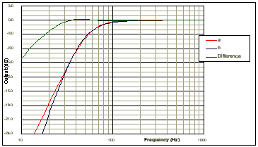
The above was generated from Brian's worksheet (Brian's link). A is a sealed box
with Fb = 55 Hz and a Q of 0.71, B is my proposed design using a 0.5 cu.ft vented box
tuned to 30 Hz, using the Peerless 1858 (fs = 22Hz, Qt = 0.23, Vas = 80l). Note how close
the 2 curves are, from 30 Hz up. Not shown is that the excursion is reduced by a factor of
2 around the 30 hz tuning f, therefore max output is increased by 6 dB in that region, and
more importantly, less distortion. Of course venteds always need a subsonic filter so I'll
put one at ~ 27 Hz. The car loses boost below 30Hz, and there is little program material
(that I listen to) that contains stuff below 30 Hz, so I'll live with no bass below 30 Hz.
I believe people are too obsessed with "maximally flat alignments"
(the "classic" alignments, as opposed to my alignment or the "EBS"
alignment) to realize the benefits of a vented, when subject to the following real world
design criteria:
- flat in-room response, down to 30Hz
- low distortion down to 30hz and specified max level (I'm happy with 105 dB,
others maybe 125dB!)
- some max box size
- Use of electronic EQ acceptable to achieve (1)
Apparently my vented alignment maximizes the above criteria better than a
sealed.
Now, as a comparison let's look what happens if we take the same box as above,
without a port:
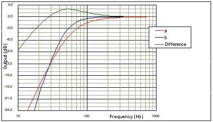
A is sealed and stuffed, giving it a 20% apparent increase in volume - note that its
output is less than the ported, from 30-80 Hz. Not shown also is the group delay of the 30
Hz tuned box is close to the sealed box (Q=0.7) down to around 30 Hz. And, it is better
than a "classic" vented box. The late Peter Mitchell suggested that the group
delay of a vented box leads to bad sound.
The prescription here: take a low Q woof; if space is a premium, set Vb to max; adjust Fb.
More techy stuff:
Driver nonlinear distortion:
I think loudspeaker designs (car and home) pay to little attention to nonlinear distortion
a.k.a. large signal response. Other stuff I've done is do simulations of a driver in a
sealed and a vented box from an electromechanical point of view. I'm a practicing analog
and power electronics design engineer, and I've used Pspice (Error! Bookmark not
defined.), a circuit simulation program, extensively. I have built a model of a driver,
complete with magnetic and suspension nonlinearity. I've had experience with designing DC
motor position control systems in the past, and I've used that experience here. With my
model I've observed phenomena like nonlinear distortion, "oil-canning", etc. One
of the things I did with that model is that I was curious about how different boxes and
tunings affect the distortion of the output. Here are my observations:
Both magnetic and suspension nonlinearity make distortion worse at large
excursions (obvious). The suspension nonlinearity influences the output more when the box
is very large. But, the magnetic nonlinearity contributes far more distortion when a tone
is played below fb, because the fundamental is suppressed but the harmonics are in the
passband of the mechanical resonance. Adding mass to the cone will lower the fb and reduce
distortion for frequencies below fb.
For sealed boxes, whenever a sine wave is played that is below fb, the
distortion products are reproduced, so the THD for tones below fb is very high. Therefore
a hipass or "subsonic" filter, even for sealed boxes, could help reduce
distortion. Therefore, a woof in a "Bag End™" alignment, could be a bad
thing for distortion. I went on to simulate vented boxes, and because of the reduced
excursion, its distortion performance was far and away much better.
Measuring BL and Cms vs. cone position
Another thing I did was measure the actual BL and Cms of a sample driver I had (a la
DUMAX, formerly used by Car Audio and Electronics), so I could check its real xmax and
enter its characteristics in my Pspice circuit to predict its performance.
I have LAUD, which can quickly extract TS params, and BL, Cms, and Mms, from the
impedance measurement of a driver. If one were to offset the cone of a driver somehow, one
could remeasure the params and get BL and Cms for that new cone position. I repositioned
the cone using an active current source in parallel to the voice coil. I derived the cone
position from the previous BL measurement. If you do this in fine enough increments you
can plot BL and Cms vs. position. The result is a poor man's DUMAX. Unfortunately I can't
write about this some more now.
Impedance vs. cone position
Other thing is I got the driver impedance for the rest position and approximately 2 and
3mm outward offset. Note the change:
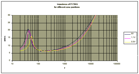
We know that a properly designed passive xover lopass filter uses the driver impedance to
yield the proper frequency response. If that driver impedance changes, the frequency
response will change. What happens if the impedance changes with position? Yup, nonlinear
distortion. The cure? #1 is a biamp setup with an active xover. #2 is to not let your
midrange driver play bass (a sub system, with a hipass on the midrange would help reduce
excursion). #3 is to design the bass-midrange unit's lopass to use a zobel, and/or an
impedance dropping resistor in parallel with the driver. In both cases the impedance
variation seen by the xover is reduced. The downside of the latter is reduced impedance
seen by the amp.
Elliptical xovers
Lastly I've tried playing with elliptical xovers, a la Joseph Audio. Elliptic filters
feature the greatest slope of the transition band for the number of parts. I believe it's
the best solution in a car, where the tweeter can be miles away from the woof. It would
reduce the frequency overlap region between mid an tweet, and thus reduce lobing, phase or
frequency funnies. I have, using CALSOD, found a hipass lopass combo that produces roughly
flat summing on-axis. I can't seem to find the circuit at the moment. When I do I'll post
it here. It will still lobe, in the overlap region, but the region is very narrow. For a
car perhaps if there is an underlap between lopass and hipass frequencies, the resulting
narrow, 1/6 octave notch is less audible than the lobing you get with the above approach.
I have an active design using 5 opamps per channel, with, in filter parlance, has 5 poles
and 4 zeros. Now I wonder why the car audio companies haven't tried it. Probably because
you can't build a tunable one easily - it would have to use swap-in circuit modules to
change the xover freq.
|
