|
Construction
The following images indicate the construction phase of my "proof of
concept" project:
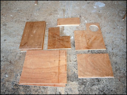
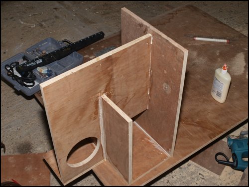
1. All of the panels cut out and ready to assemble. It
took about half of a 4x8 panel of 3/4 ply to produce these panels.
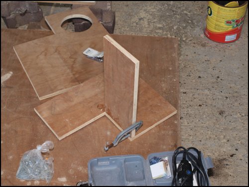
2. Putting the first two panels together. I started with the front
panel (facing downwards in the image above and one of the internal panels.
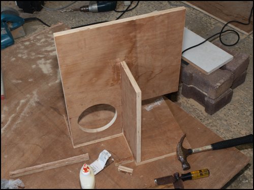
3. Attaching the third panel. This is the
one that will eventually host the driver.
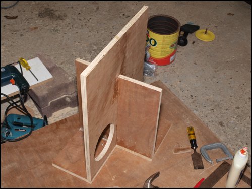
4. Attaching the 4th panel (which identical to the 2nd panel). The path that
the pipe is going to take inside the enclosure should be clear from this and
the previous picture.
5. Attaching on side.
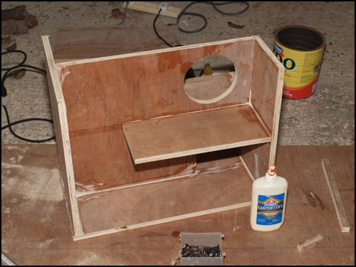
6. Attaching the back panel.
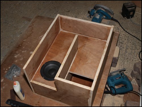
7. Attaching the other side panel and the bottom panel. Now the internal
structure of the pipe should be pretty clear.
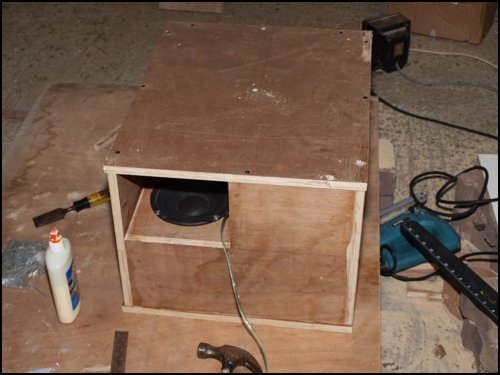
8. Closing up the box. Instead of permanently sealing up the box, I
opted to use screw the panel in and use a thin strip of weather sealing to
ensure an airtight seal. This will allow me to take apart the box in the
future if I want to add any stuffing or otherwise change the box's
internals.
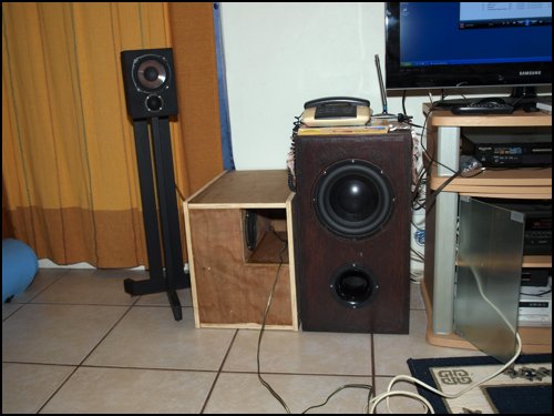
This picture should give a good idea of the size of the finished box.
Here the tapped pipe box is located next to my ACI SV10 subwoofer.
This is a pretty large box for a 6.5" driver. When compared to direct
radiator alignments, size is definitely not one of the tapped pipe's
advantages. In these days of large drivers and cheap amplification, it's
probably easier and better to go with a director radiator alignment for home
or home-theatre use, unless there's a specific reason why you want to
attempt one of the high-efficiency alignments like a tapped pipe.
Brian Steele
12 October 2018
|