The Subwoofer DIY Page - Projects
"El Uglito" - a 4th order bandpass system
03 February 2019
This project is a 4th order bandpass isobaric system based on two Pyramid W61 6.5" drivers. "Isobaric" basically means here that the drivers are mounted face to face with the connections to one driver reversed, the idea being to reduce by half the volumes required for the sealed and ported sections of the system.
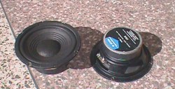
The driver
Why Pyramid W61 drivers? Well, basically I had two of
them lying around the house, doing nothing. I'd pulled them from my car
a few months ago, where they were doing a decent job of rear fill when
free-air mounted on the rear package tray.
The W61, like most car audio drivers, is pretty solidly built, but the cone is made of paper and is basically too soft to do any serious thumping. Pyramid didn't provide any Xmax specifications for the driver, but the cone does have about 0.5" of excursion before the suspension brings it to a dead halt. For my calculations, I guestimated an Xmax figure of 0.1 in. Pyramid DID provide figures for Vas (19 litres), Qts (0.47) and Fs (64.5 Hz), but a quick check of the drivers showed that the published specs were a bit off. Average Fs for the two drivers checked in at 52Hz, quite a bit below the published spec, which is nice as it means that I should get a bit more bass out of it.
The average Qts for the pair of drivers checked in at 0.50, and the average Vas at 'round 28 litres or so. No probs - the lower Fs and higher Qts suggested to me that the W61 could give decent results in a sealed or 4th order bandpass system. I'd expected the measured specs to be different anyway, as I'd quite recently replaced the original dust covers for the drivers with some new ones that I'd purchased locally.
Choosing an alignment
Now the bad news.
The specs for a single W61 driver indicated that, for a sealed system with a Qtc of 0.71, the net box volume would have to be about 28 litres (almost 1 cu.ft.), pretty big for a 6.5 incher. The F3 would also be around 73Hz, which isn't so hot either. An isobaric system using two drivers would reduce the net volume to 15 litres, but the cutoff frequency would still be a bit too high for my tastes.
In steps the 4th order bandpass system!
My calculations showed that a single W61 used in a bandpass system could give a pretty decent response, but the resulting box would be pretty big. My intuition also told me that the power handling wouldn't be so hot because of the driver's limited Xmax (rule #1 - bigger is NOT always better!).
An example of a 4th order bandpass alignment using one W61 driver would be as follows:
    Vf = 13.9 litres
   Vr = 27.2 litres
   Fb = 74.3Hz
   Fl = 45.7Hz
   Fh = 120.7Hz
   Gain = 0.00dB
The 4th order bandpass alignment above has a pretty good
cutoff point for a 6.5 incher, but the Xmax for this driver is pretty low,
so I may not get decent output at that frequency. The box size is also
pretty big, at about 41 litres (1.4 cu.ft.) total.
Here's where the flexibility of the 4th order bandpass design steps in!
Say we use an isobaric system to decrease the volume requirements, then reducing the size of the rear volume even further by settling for a higher cutoff frequency? With this in mind, I fudged around with the calculations again and came up with the following alignment:
    Vf = 7.0 litres
   Vr = 9.9 litres
   Fb = 81.2Hz
   Fl = 52.0Hz
   Fh = 126.9Hz
   Gain = 1.56dB
The cutoff frequency of 52 Hz indicates that this 4th order bandpass system can't be described as a proper subwoofer, but that's OK because the limited Xmax of the W61 indicates that it shouldn't be used in a very low frequency application anyway. However, the cutoff frequencies do indicate that it'll make a good woofer element for a small three-piece system, so I decided to go ahead and give it a try to see what it sounded like.
Designing the box
Designing the box for a 4th order bandpass isn't difficult,
once you take certain precautions. First of all, you MUST account for the
volume occupied by the drivers, port, bracing and any other items that
are going to be enclosed in the box! This becomes even more critical when
designing small enclosures, as the volume displaced by the drivers and
the port could have a significant effect on the final dimensions of the
enclosure.
Designing the box - the vented section
Bandpass systems usually suffer from out of band noise,
but the effects of this can be reduced by taking appropriate steps in the
design of the vented section. The steps that have worked for me in the
past include:
- Orienting the driver so that its magnet structure is located in the vented section
- Placing the driver asymmetrically within the enclosure
- Placing the port so that the driver is not visible through the port
- Line the ported section using fiberglass or similar damping material
There is one potential problem here - the damping material may increase the effective size of the vented section and lower Fb, the resonance frequency. I didn't foresee this being much of a problem, however, as I could reduce the effective volume by adding additional braces to bring the resonance frequency back up to specification. I decided to opt for a vented volume that was slightly more than that required for the alignment. If necessary I could use bracing and/or damping material to make any further adjustments.
Designing the box - the sealed section
Designing the sealed section was even easier. Using fiberglass
or another damping material in the sealed section leaves me with some leeway
in the design, as the effective size of the section can be varied by adding
or removing damping material. I opted for a sealed section equivalent to
the calculated value for Vr. The bracing and the volume displaced by the
driver would reduce the volume, but damping material could be used to counteract
the reduction.
Designing the box - response variations
After thinking about it for awhile, I worked out
that the conditions listed below may occur in the design and affect the
output as indicated. I put together an action plan for each scenario. It's
always best to work out all of these details BEFORE you actually start
cutting wood, and save yourself unncessessary headache afterwards!
- Vented section too large.
- Result: narrow bandwidth; higher cutoff frequency.
- Action: reduce Vf by adding bracing in the vented section.
- Vented section too small.
- Result: wider bandwidth, non-flat bandpass characteristic, degraded transients.
- Action: add damping material to vented section.
- Sealed section too large.
- Result: lower efficiency, response peak in upper frequencies.
- Action: remove damping; add bracing to sealed section.
- Sealed section too small.
- Result: higher cutoff point; response peak at lower frequencies.
- Action: add damping material to sealed section.
Designing the box - the final plan
My final battle plan for the project was as follows:
Determine Lv, the length of port of diameter Dv, required to tune Vf, the vented section of the enclosure, to Fb.
Build the enclosure such that Vf', the gross volume of the vented section, is slightly more than Vf, the net volume predicted by the calculations. Also, Vr' the gross volume of the sealed section, will be equal to, if not slightly less than, Vr, the net volume predicted by the calculations.
Add a port of length Lv and diameter Dv to the vented section. As Vf' is more than Vf, the tuned frequency of the vented section should be lower than that called for by the calculations.
Add bracing/damping to the vented section until the tuning frequency is equal to Fb, the tuning frequency predicted by the calculations.
Add bracing/damping to the sealed section until a flat bandpass characteristic is obtained.
At this point, the 4th order bandpass system should have a frequency response that is as close to ideal as I can get.
Building the box
This is what the finished product looked like, from
below (with the bottom removed):
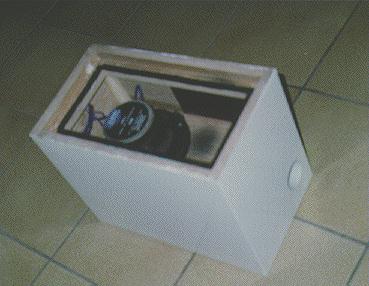
The drivers were mounted from below, in the sealed section of the enclosure. The bottom of the sealed section was made removeable, so that the drivers could be accessed at any time. The bottom of the enclosure would be facing the floor when the system is in its normal position, so no screws are visible. Vf is 7.5 litres, and Vr about 10 litres. 3/4 marine ply, butt joints and aliphatic resin (wood glue) was used throughout. Drywall screws were used to hold the sections together while the aliphatic resin dried, then they were removed and the holes filled with wood filler. The enclosure was then sanded and painted with a white laquer (basically to stop the ply from splintering along the edges!). Tuning was done as outlined in the previous sections.
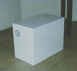
This is what it looks like from the front:
Final Results
The final results are pretty good, if I do say so myself.
The passband is very close to the predicted 52 Hz-126 Hz, and the noise
band is pretty low in level - the highest point is 11dB below the passband,
and the noise is virtually inaudible when the system is used along with
two Mordaunt-Short 3.2's that I employed temporarily as satellites. A full
frequency response check on the system shows that there's a very slight
peak in the lower section of the passband ('round 60Hz or so) but that
can easily be fixed by adding a bit of bracing to the front chamber to
increase the tuning frequency. So far it isn't bothersome, so I haven't
bothered to add the bracing.
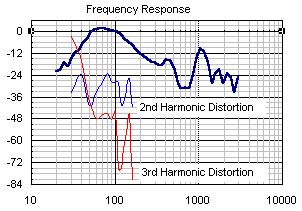
Notes:
- The peak at 1 kHz is the port resonance (a "feature" of almost all bandpass systems), and can be cured by a simple notch filter. So far I haven't found it bothersome (probably because I'm driving the system using an active filter in the amplifier).
- The small ripple at 450 Hz is caused by reflections from within the box, probably from the back panel, which is parallel to the port openings. The peak was reduced considerably by the addition of damping material in the front section - which in turn is probably causing the slight peak in output at 60 Hz, because the tuning of the front section has now been altered!. However, the slight bump at 60 Hz is a lot less objectionable than a huge peak at 450 Hz...
- The slight ripple at 27 Hz I believe was caused by a small leak in the sealed section of the system, which I subsequently fixed.
- The 2nd and 3rd harmonic distortion readings were taken at a drive level of 2.83 volts to each driver in the system, and the results were measured relative to the output level of the fundemental frequency at this drive level. At this level, the system was generating over 120 dB at the port in the middle of the passband. The rapid rise in 3rd harmonic distortion below 50 Hz is caused by the drivers exceeding their Xmax at this volume level.