Transmission Line Systems
12 March 2024
The transmission line system is a "direct radiator" alignment that is designed to use the 1/4 wave resonances in a waveguide to enhance and extend its useful range of operation. The waveguide reverses the phase of the driver's rear output by the time it reaches the terminus, thereby reinforcing the output near the lowest resonance frequency of the waveguide. Transmission lines tend to be larger than the other systems, due to the size and length of the line required by the design. The payoff is an extended low end response and a characteristic sound that's appealing to many. The better transmission line designs also take the waveguide's other resonance modes into consideration, as these will otherwise impact the design's useful range of operation.
There is a lot of information about transmission line speakers available on the Internet, but unfortunately a lot of that information is either based on "classical" transmission line design (which is basically obsolete), and/or is just flat out inaccurate. Fortunately these days there are quite a few software tools (including the freeware Hornresp tool) that can be used to simulate transmission lines, which makes the design process a lot easier.
Note also that the design process for a "full range" transmission line speaker is likely going to be quite different to the design process for a transmission line subwoofer. That's primarily due to the fact that you will need to suppress resonances in the former by stuffing and/or lining the box because you don't want those resonances coloring the response of the speaker, while in the case of a transmission line subwoofer you would likely try to avoid stuffing it as much as possible because any stuffing in the box will reduce the output at low frequencies. As this is a site for designing subwoofers, it will concentrate on the latter approach.
Usually, only drivers which have low Qts (0.25 - 0.4) , Qes (0.3 - 0.4) and Fs values are suitable for transmission line systems. However higher-Q drivers can be used. Just ensure that you simulate the results in a proper modeling program first before committing to a build!
Transmission line enclosures are usually a bit more complex to build than your common vented box, and you should spend a lot of time making sure that your simulation is correct before committing it to wood to make sure that you're not disappointed with the results.
There is a variant of the transmission line called the mass-loaded transmission line. This is basically a transmission line that is terminated by a vent. There are several advantages to using this approach, including addressing the pipe resonances along the line and reducing the box size without giving up any noticeable output at low frequencies.
Design Notes:
For these
design notes, I will step you through the design process. My tool of choice
for designing transmission lines is Hornresp. There may be better
tools out there, but Hornresp is simple to use (once you learn how to use
it!) and the results are close enough to be useful for most purposes.
Choosing the driver:
For this example, I'm going to use the Dayton Audio PA310. This is a
cheap but decent quality 12" pro audio driver with a nice low Fs and Qts,
making it suitable for a number of different designs.
The
specifications of the PA310 are as follows:
Sd = 530.9 cm^2
Re =
5.2ohms
Fs = 39 Hz
Vas = 99.27 l
Qes = 0.31
Qms = 7.51
Qts =
0.30
Le = 1.4 mH
Xmax = 5 mm
"Classical" transmission line
theory suggests that an appropriate transmission line configuration for this
driver would be one that is long enough to resonate at 39 Hz, and has a
constant cross-sectional area of 530.9 cm^2. But what would the
response of such a design be like?
Enter Hornresp, which can be used to simulate such a build.
The following image shows the parameters for a Hornresp sim of this "classical" type of transmission line. Note: to enter Cms, Mmd, BL and Rms for the driver, simply double-click on the "Sd" text box - a dialog box will pop up asking you for the t/s parameters for the driver, and Hornresp will use these to calculate the other parameters it uses. Note also that I have selected an "OD" (offset driver) simulation for this build - the reason for this will be explained later! As for "Vrc", "Lrc", "Ap1", "Lp", "Vtc" and "Atc", I've set those values to zero - we're not going to be using them for this simulation.
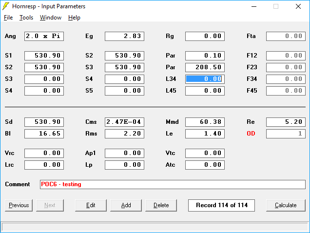
A brief outline of what's shown in the sim above:
Ang -
for comparison purposes, this shouild always be set at "2.0 x Pi", which
basically represents a speaker sitting on the floor
Eg - the voltage
that's being applied to the sim, 2.83V
Rg - the resistance of the cable
(which I've set to zero for the purpose of this sim)
S1 - the
cross-sectional area at the start of the transmission line (in cm^2)
S2 -
the cross-sectional area where the driver is located (in cm^2)
Par (1) -
the distance between S1 and S2 (in cm)
S3 - the cross-sectional area at
the end of the transmission line (in cm^2)
Par (2) - the distance between
S2 and S3 (in cm)
So far, so good. At this point, we can select
"Tools...Loudspeaker Wizard", and check what this sim is going to look like
.png)
Ok, that looks like what a "classical" TL would look like, with the driver (the red circle) at one end and the vent at the other. Now, let's see what the predicted response of this sim looks like...
.png)
Ugh, that looks pretty bad. The resonance frequency is where we expect it to be, but there's this massive notch in the resonse between 100 Hz and 200 Hz. Why is that? Well, because of resonances along the transmision line. That's because the transmission line does not resonate at one frequency - it resonates at many frequencies. We can see what the result of this looks like by looking at "Output 1", not the "Combined" output...
.png)
So, we're now looking at the response from the vent alone. See that big peak between 100 Hz and 200 Hz? that's one of the resonance frequences of the straight transmission line, and if look closely you'll see that it's three times the lowest resonance frequency, 39 Hz, which works out to 117 Hz. This resonance is out of phase with the driver's output, which results in the big notch that you see in the "Combined" response. This is why building a transmission line subwoofer with a constant cross-section with the driver at one end and the vent at the other is so bad - it introduces this huge notch in the response that basically limits the effective passband of the subwoofer.
So, how do we deal with this notch? Well, one effective way is to simply locate the driver partway down the line rather than right at the end. Let's see what happens when we do that...
.png)
So here's what the response looks like with the driver moved to 73.1 cm down the line (now do you see why I chose the "Offset Driver" type of Hornresp sim?). The notch between 100 Hz and 200 Hz has now been eliminated, and the sim shows a response that extends up to 200 Hz before the next notch appears. Note that there is a peak at 200 Hz, but in reality this peak will not be so high as Hornresp does not include the impact of box losses in its sims.
At this point we could stop here, but I want to refine this build a bit. First of all, a resonance frequency of 39 Hz is a bit too low for this driver (it only has 5mm Xmax, and will run out of excursion fairly quickly in its passband in such a large box). There is also a small hump in the response at the lower end of the passband, which suggests that the response of the subwoofer will be slightly "under-damped" at that point. Some people don't mind this. I do, so I tend to adjust my sims to eliminate it. So, let's adjust the sim to bring the lowest resonance point up to 48 Hz, and see if we can remove that slightly under-damped response as well. To do the former, we need to shorten the path, and to do the latter we need to decrease the cross-sectional area of the transmission line.
.png)
Ok, this looks a bit better. The under-damped response at lower frequencies is now gone, and the resonance frequency has been moved up to 48 Hz. The takeaway for this is (1) you don't HAVE to set the resonance frequency of the transmission line to be the same at the resonance frequency of the driver, and (2), you just might get better results using a smaller cross-sectional area than "classical" transmission line theory suggests (in this case 411 cm^2 instead of 530.9 cm^2), and end up with a smaller box with better performance to boot.
The challenge at this point is going to be trying to fold up this transmision line into a box that puts the driver in the correct location down the path. Sometimes this can turn out to be quite difficult to do, as the driver might end up being having to be placed around a corner to be at the correct distance from the start of the path, and this might be impossible to implement. In this case, the driver will have to be located 59.3 cm from the start of a path that's a total of 168.6 cm long, so if the line is folded to have the vent come out on the same side of the box as the driver, we might run into this difficulty. So, what can we do?
.png)
To tackle this problem of driver placement, I've modified the Hornresp simulation a bit. I've split it into three sections, so instead of S1, S2 and S3, I now haveS1, S2, S3 and S4, where S4 now represents the cross-sectional area at the vent.
I'm now going to change the transmission line from a straight transmission line to a tapered one by adjusting S1 and S3 and load it with a straight vent represented by section S3-S4. This converts it into a mass-loaded transmission line. Note that there is an "Auto" right next to S2 - this means that Hornresp is automatically calculating the value of S2 for me (to keep the taper from S1 to S3 constant). The default is "Manual" (self-explanatory), but by double-clicking on S2, I've changed it to "Auto".
.png)
Note now that the driver is now at 49.6 cm from the start of the transmission line, which may be short enough to ensure that it doesn't have to be located on a corner (if the line is folded). So, what does the response of this modified version of the transmission line look like?
.png)
That actually looks a bit better. Not only does the response at the low end remain the same, but the response at high frequencies is a bit smoother - the notch in the response at 300 Hz has been moved up to around 350 Hz. In fact, you will find that if you increase taper (by increasing S1) and adjust the rest of the parameters to ensure that the resonance frequency remains the same, the aberrations at the upper end of the passband will move further up in frequency. The downside here is that you will likely have to reduce the cross-section of the vent in the process, and this will reduce the output of the subwoofer at high SPL levels. To prevent this "vent compression" effect, I recommend not reducing the vent cross-sectional area any less than 1/3rd of the driver's Sd, and keeping it above that if possible.
Transmission Line resources and projects on the internet:
- Quarter Wavelength Loudspeaker Design
note: different nomenclature used on the above site
translation as follows:
fd = Fs
Qes = Qes
Qmd = Qms
Qtd = Qts
Vd = Vas- Transmission Line Speakers
- POC6 - a 48 Hz mass-loaded transmission line
- The Boom Unit
- POC7 - a 40 Hz straight transmission line