INF10 dipole subwoofer
27 January 2019
This is really a side-project that came about while I was constructing a 4th order bandpass alignment for a spare INF10 driver that I had lying about. Halfway through the construction process, I noticed that the partly-completed box looked quite a lot like an 'H' baffle for a dipole subwoofer. It therefore seemed a good idea then to use the opportunity to test the INF10 in a dipole alignment using the partly-completed box, just to see if the actual frequency response was a close match to the response predicted by the dipole spreadsheet.
Here's a picture taken partway through the construction process, showing the box before the top and bottom panels were added and the cutouts made for the vents:
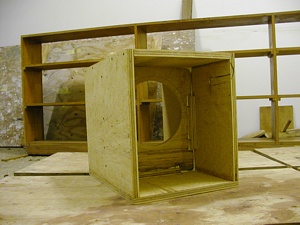
You'll notice that the box strongly resembles an 'H' baffle for a dipole woofer alignment.
The measured T/S parameters for my INF10 driver are as follows:
| Vas | 127.4 litres (4.50 cu.ft.) |
| Qes | 0.32 |
| Qts | 0.31 |
| Fs | 20.3 Hz |
The dimensions of the 'H' baffle are as follows:
| Length | 15.00" |
| Width | 12.50" |
| Depth | 19.00" |
From my frequency measurements below, it looks like the "effective diameter" of the 'H' baffle worked out to be 59 inches . Plugging that an the T/S parameters of my INF10 into my dipole spreadsheet, the following frequency response is predicted:
Not a very nice-looking graph for a woofer alignment, but the intention here is only to determine how close the predicted response matches the measured response.
The measured response (with the dipole system located a few feet from one corner of my living room, directly facing the mike, and the mike located at ground level near my usual listening position) is as follows:
Ugh! I thought that dipole bass systems were supposed to be relatively immune from room modes? The measured frequency response of this dipole suggests that this is certainly not the case! In fact, quite the opposite.
I tried repeating the measurements, with the dipole bass system mounted at different locations. Here's the frequency response with the system at the same location as above, this time with it turned so that the "null" was facing the mike:
And finally, here's the measured frequency response for the system with it located along one of the side walls (as recommended by some), again with the mike at ground level at the listening position:
Apparently the bass response of the system has been flattened and extended quite a bit with this mounting location, indicating that there is some merit to this suggested positioning. However, the rolloff is now quite a bit steeper, and room modes are still visible in the response curve.